
Specialised Testing Capability
Scanning Microscopy and EDAX
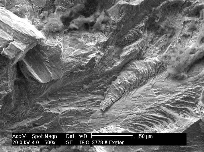 Scanning Electron Microscopy with Energy dispersive x-ray spectroscopy (SEM – EDAX) provides a surface analytical technique that delivers high resolution images of surface topography with excellent depth of field. It can be used to analyse fracture components, contaminants, and bearing surfaces as well as wear debris in biological tissues.
CITRA has been a user of SEM technology since its first introduction to RPH in the 1970s. Specialised studies have been conducted in co-operation with the Department of Pathology (now PathWest) and the University of WA using a combination of transmission microscopy (TEM), SEM and adjunct EDAX capability providing fractography and ultrastructural studies and elemental analyses involving the implant device and tissue affected by the device. SEM technology has developed, allowing routine studies to be conducted in-house at the desktop level. The current SEM has a specimen volume of 70 x 50mm max, magnification in the order of 10x to 60,000x and an analytical capability including EDS, high and low vacuum modes, suitable for routine use with metal devices, fracture and wear surfaces and for developmental substrates such as ceramics and tissue engineered product.
The introduction of JOEL KCM 6000 SEM/EDAX desktop capability has been facilitated with a capital grant from the Royal Perth Hospital (RPH) Research Foundation.
Elemental analysis
Elemental analysis is provided by a multi-channel, high speed analytical spectrometer designed for instantaneous, multi element analysis.
The Ametek Optical Emission Spectrometer (OES) enables accurate alloy/grade identification of metal devices:
- To qualify candidate implant devices against the relevant standards.
- To qualify materials intended for custom made devices, ensuring compliance with the relevant standards.
- To test failed implant devices for standard compliance.
Metallography
Metallography enables examination of the micro-structure of the metals used in implant manufacture. These structures reflect the composition of the alloy and the effect of manufacturing techniques that can be beneficial (e.g. fatigue resistance) or which may otherwise render the device susceptible to failure (e.g. intergranular corrosion).
Biomaterials and in particular the metals used in implant manufacture (e.g. the stainless steels, cobalt and titanium based alloys) are designed to be resistant to degradation within the hostile environment presented by the body. This in turn makes them difficult to prepare (e.g. by polishing and etching) to enable the microstructures to be seen under the microscope. CITRA has a comprehensive laboratory, equipped to prepare metallic and ceramic materials for section, embedding, grinding/polishing and etching and hardness testing. Microstructures can be evaluated using optical microscopy (including specialised techniques such as polarising and phase contrast), macro and microhardness testing and ultrastructural analysis using scanning electron microscopy. Studies are recorded using digital macrography for reporting and archiving.
Surface evaluation and measurement (Co-ordinate Measurement – CMM)
CMM enables an accurate measurement of the worn and/or corroded surface which, when compared with the shape projected from the original (i.e. unworn) surface can provide a volumetric estimate of the implant material deposited into the surrounding tissue structures.
Adverse reaction to devices in the body and the integrity of the device itself is compromised by the effects of corrosion (chemical and fretting) and the wear of the device. In the latter case, severe reaction can be elicited in the host tissue by the deposition of wear product in to the tissue. Wear rates are determined by the bearing materials (e.g. metal on polymer, metal on metal), the dynamic load on the device and there is potential for abnormal wear patterns related to design and the surgical alignment of the device. Together these determine the amount of metal debris deposited into the tissue, as a precursor of adverse tissue or host reaction.
CMM enables an accurate measurement of the worn surface which, when compared with the shape projected from the original (i.e. unworn) surface can provide a volumetric estimate of the implant material deposited into the surrounding tissue structures. Importantly, this estimate forms the basis for an objective and quantitative analysis linking the wear with the extent of tissue reaction and the clinical outcome for the patient. The Ortholux system is based on the chromatically encoded confocal measurement method that allows visualising the wear scar and calculating volume wear loss using a validated method. Wear studies can be performed on complex surfaces such as the knee and for taper surfaces on modular devices.
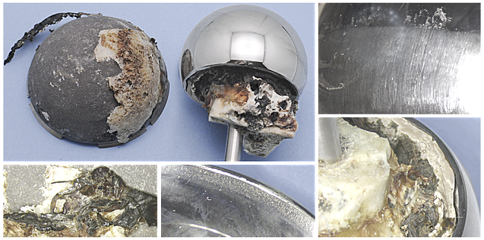
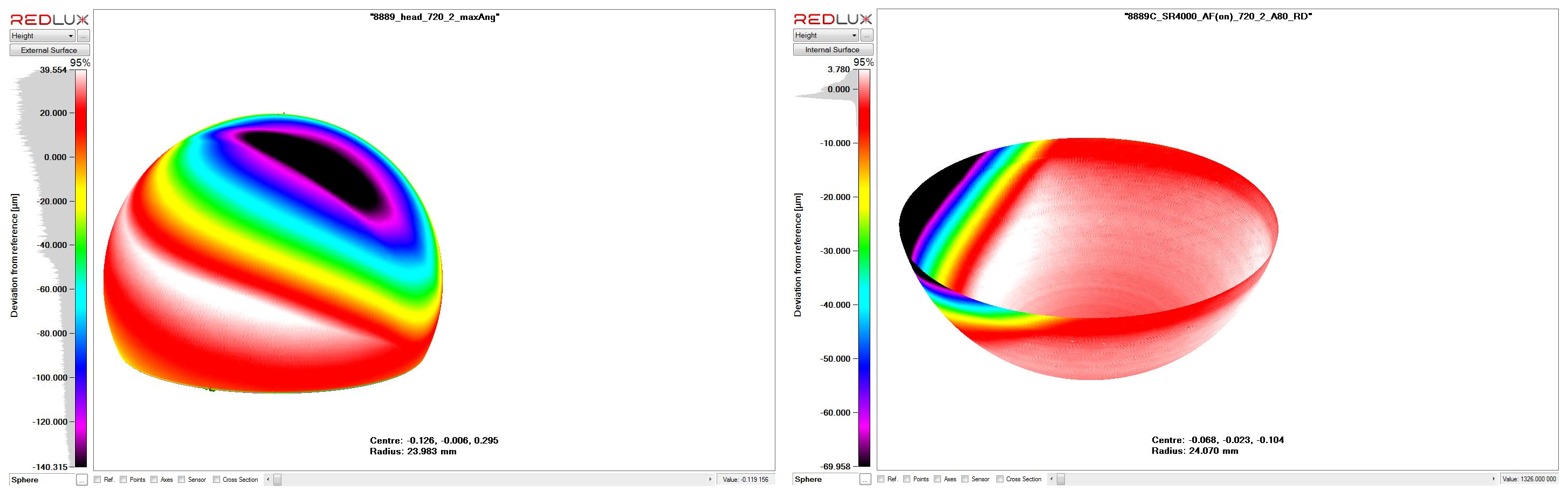
Above is an example of metal on metal wear on a retrieved hip arthroplasty. Below are the CMM scans which indicate related wear on the femoral and acetabular components, allowing an estimate of the volume of wear debris introduced to tissues surrounding the device in-situ.
Mechanical testing
The mechanical strength of an implant device is central to its performance within the body and its longevity. Mechanical strength and the devices resistance to failure mechanisms such a brittle fracture, notch sensitivity and fatigue are a product of design, material selection, manufacturing processes and the load environment expected under normal use. Each of these conditions can be tested within the laboratory as a precursor to design or for candidate device investigation and selection and/or failure analysis.
The testing laboratory has three instrument capabilities:
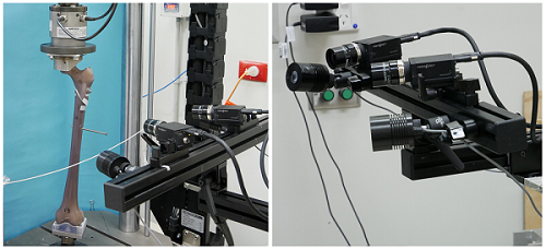
- Instron 8874 Servo-hydraulic Testing Machine (pictured):
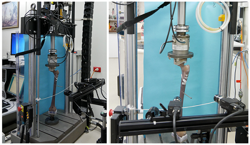 The servo-hydraulic machine has a load capacity of +/-25kN and +/- 100 Nm torsion with load cells down to +/- 1kN and 25Nm and a travel of +/- 50mm. The 8874 allows for high strain rate testing of prepared samples and implant devices and is suitable for limited fatigue testing.
 - Instron 5566 Electro-mechanical Testing Machine: The electro-mechanical machine is suitable for a wide range of tensile/compression testing with loads up to 10kN. While strain applications are limited to 500mm/min the 5566 offers the advantage of a well constrained and controllable testing environment suited to use by students, surgical registrars and laboratory staff not familiar with the servo-hydraulic testing environment.
- Instron 5848 Microtester: The microtester is also an electro-mechanical device with a load capacity up +/- 2kN and high resolution displacement of 0.02 micrometer. The instrument is suited to tensile and compression testing at the lower end of the scale using 100N and 10N load cells making it suitable for the testing of biological materials, anatomical structures and polymers. The machine provides for portability (e.g. testing outside the laboratory in a theatre situation) and offers the flexibility of testing with the load axis variable between vertical (usual) and horizontal. This instrument was provided for research with the support of the Royal Perth Hospital Medical Research Foundation.
The use of the testing facility for a range of research and routine laboratory investigations over 40 years has resulted in the development of a wide range of adaptations and fixtures suited to testing of engineering materials and biological tissues and tissue structures. Specialised fixtures are designed and manufactured in-house (advanced manufacturing), drawing on the experience of the CITRA team. Testing regimes reflect the need for compliance with international and Australian Standards. This custom capability is assisted with access to:
- Environmentally controlled testing environment:
 The testing laboratory can be isolated from the building air conditioning to allow limited independent control of temperature if required. For example; when testing the use of sutures it was found advantageous to reduce the laboratory temperature to simulate the operating theatre temperature as one of the possible factors affecting suture performance. This is an alternative to the use of specialised testing chambers which limit access to the test sample.
 - Optical strain measurement (pictured): The VIC-3D system enables the measurement of strain in the range 0.005% to > 2000%, without the requirement for contact with or attachment to the test sample. This is critical for tissue, biological samples and small test specimens where the interactive effect of attaching a strain measurement device (e.g. strain gages or extensometers) and driving it may adversely affect the performance of the sample.
- Strain Gage instrumentation: based on 6 channels of resistance strain gauge signal conditioning.
Thin section preparation for metal-tissue substrates
Instability at the interface between host bone and the implant device, resulting in loosening and with potential for fretting and crevice corrosion of the device, remains a significant failure mechanism requiring revision of the procedure. The CITRA laboratories have developed a methodology for the preparation of thin sections involving metal-tissue substrates, allowing assessment of the interface at a microscopic level and at a thickness consistent with histological evaluation.
While assessment of the interface between cemented devices and bone is important, it is of particular importance in the range of appliances where fixation of the device relies on the in-growth of bone into the interstices manufactured on the surface of the implant device. Typically the interstice size is designed to be conducive to cell health and propagation and in-growth must be sustained over an area that is able to carry the loads required during load bearing and ambulation.
In contemporary devices in-growth may be enhanced by the use of bone growth inducing substrates (such as hydroxyapatite compounds) applied to the interface surface. Individually, the techniques for preparing metals (e.g. stainless steel, titanium and cobalt based alloys) and tissue (e.g. bone and soft tissue) for microscopy are quite different – with metallography being based on reflective examination with the juxtaposed tissue requiring transmission microscopy of a stained section.
The challenge is to cut a ‘thick’ section (approximately 300 micron) from across the interface while maintaining the integrity of both the metal and the fixed tissue within the section. This must be maintained while polishing the section to a thickness of typically 100-150 micron. Implant alloys present a particular challenge during preparation, with the propensity to harden during grinding and polishing.
The quality of the section produced in the hands of the laboratory at RPH has been acknowledged internationally.
 |
 |
 |
||
|
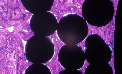
Ti beaded porous coating (Mag. 12x) Geimsa Stain indicating infiltration of lamellar bone. |
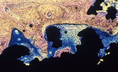
Ti Plasma spray coating (Mag. 20x) Staining indicating fibrous tissue surrounding the porous coating with lamellar bone on the surface. |
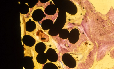
Ti mesh coating (Mag. 10x) Geisma stain indicating fibrous tissue surrounding the porous coating with lamellar bone on the surface. |
Accelerated corrosion testing
Corrosion
Corrosion presents a significant risk to implant devices despite the introduction of increasingly inert and resistant metals used in the manufacture of devices. Corrosion is an electro-chemical process, comprising dissimilar metals that form a galvanic cell producing an electrical current in the presence of a supportive electrolyte. Modern alloys (e.g. stainless steel, cobalt based and titanium alloys) are designed to establish robust passivation layers that protect the alloy by reducing the current that is maintained by metallic corrosion, resulting in dissolution of the primary alloy. There are a number of contributing factors that can accelerate this process including mechanisms such as fretting, intergranular and crevice corrosion. These factors are affected by material selection and implant design, particularly where the device is multi-component and subject to variable and cyclic loading.
Tissue reaction
Corrosion in the body has the double effect of reducing the strength of the device through material dissolution and by introducing metal saturation in the electrolyte and the subsequent deposition of metal solutes into the tissue. This can cause varying degrees of adverse response and pathological change within the tissue depending on the bio-compatibility profile of the parent material and the corrosion by-product.
Testing
Corrosion is by nature a slow process, particularly where increasingly resistant materials are used in implant design. Accelerated corrosion testing provides a method to rapidly characterise the corrosion (or electro-chemical) profile of a material by driving the cell with a potentiostat that produces a controlled potential across the cell and a measure of the current density developed between the test material and a reference (platinum) electrode. The use of standard reference anodes and electrolytes enables comparison of the performance of the test material (e.g. high nitrogen stainless steel) with known materials (e.g. 316L grade materials). This baseline can be compared with a similar cell where the electrolyte is varied to simulate a tissue environment, which provides an estimate as to how the material may perform under idealised implant conditions.
Advanced techniques
While accelerated corrosion testing provides a useful baseline characterising the material it does not necessarily provide an accurate assessment as to how the implanted material will perform in practice. It is important that additional testing is undertaken to determine the implant devices resistance to the practical effects of mechanisms, such as fretting and crevice corrosion encountered in practice. CITRA works closely with Curtin University (external link) in the development and application of this technology to implant materials.
Archived reference material
Devices referred to CITRA following removal, including those devices removed as a routine, are evaluated and recorded. The record identifies the type of device and its clinical service (e.g. patient, surgeon, reason for removal). In addition, any observations indicative of mechanical or material degradation (e.g. wear, corrosion, tissue reaction) are recorded, including those cases where implant failure has not necessarily required removal of the device. Critical devices (such as arthroplasty) are individually packaged, stored and cross referenced in the laboratory database. Trauma fixation devices are evaluated and recorded but storage space limits archiving to those devices where a failure has occurred or where there may be other noteworthy observations.
In the case of a particular referral due to failure of the device and/or concern on the part of the clinician or the laboratory that a pattern of risk to the patient is developing, the laboratory has the capacity to retrospectively access a number of previously stored items to support a current investigation. Importantly, in-depth laboratory investigation based on a cohort of devices is critical in determining a possible causal relationship between the device and clinical failure and provides guidance as to remedial action that can be taken (e.g. technical, manufacturing, device selection or surgical methodology) in reducing risk to current and future patients. This investigative capability is a particular strength of the CITRA service.
Access to pathology services
The anatomical pathology services provided to RPH have been essential to the development and delivery of many laboratory services provided by CITRA in relation to bio-materials, implant failure, tissue reaction and bio-compatibility studies. Access to patient related investigation and the provision of adjunct studies specific to device related laboratory investigations contribute to the range and depth of assessments provided to clinicians by CITRA. These include both conventional and electron microscopy.
DefinitionsCrevice corrosion: Can occur due to pitting or as the result of design and manufacturing constraints that form crevices on the surface, wide enough to allow penetration of solutions but narrow enough to support localised oxygen depletion or chloride concentration differences in the electrolyte within the crevice. Back to accelerated corrosion testing. Cyclic polarisation testing: Employs a potentiostat that varies the potential maintained across a standardised cell and measures the electrical current carried by the cell. The polarisation curve, a cyclic plot of current density against the electrode potential characterises the material, for example by identifying the potential at which the passivation layer breaks down and the current density (i.e. the dissolution of metal ions into solution) that arises in the stable cell and subsequent to failure of the passivation layer developed by the test material. Back to accelerated corrosion testing. Fretting corrosion: Occurs due to micro-movement between surfaces in contact that results in destruction of the passivation layer due to wear and the subsequent exposure of the base metals to progressive electro-chemical attack. Interfaces between mating components that are subject to cyclic loading (e.g. screw-plate interfaces, tapered mating surfaces) can be susceptible to fretting corrosion. Back to accelerated corrosion testing. Galvanic corrosion: Occurs when two dissimilar metals are in contact in the presence of an electrolyte, forming an electro-chemical or galvanic cell. Each metal will develop an electrical potential in the electrolyte, determined by its position in the electro-chemical series (ECS). The corrosion rate depends on the conductivity of the electrolyte (i.e. its capacity to sustain a current), the relative positions of each metal (electrode) on the ECS and the ratio of surface areas between the metal electrodes. Back to accelerated corrosion testing. Intergranular corrosion: A selective attack in the vicinity of the grain boundaries of an alloy, particularly in the presence of segregated impurities or due to elemental variation at or within the grain boundary. For example, in a stainless steel this could be as result of chromium depletion due to the precipitation of chromium carbides in the grain boundaries. The electro-chemical differences adjacent to and involving the grain boundary causes galvanic corrosion often resulting in sacrifice of the material, typically at the boundary and grain dislodgement contributing to progressive failure of the material. Back to accelerated corrosion testing. Metallic corrosion: The chemical reaction where a metal surface reacts with its environment to form a more chemically stable compound such as the metal oxide, hydroxide or sulphide. Self-passivation, or the extent to which the reactive layer is stable and shields the prime metal from further attack, determines the rate of corrosion. Back to accelerated corrosion testing. Passivation: Refers to the creation of a protective and stable layer on the surface of a material by a purposeful chemical or oxidative process. Back to accelerated corrosion testing. Pitting corrosion: A form of localised corrosion, which produces attacks in the form of spots or pits. Back to accelerated corrosion testing. Stress corrosion cracking (SCC): Characterised by cracks propagating either transgranularly or intergranularly (along grain boundaries). There are several types of SCC, for example, chloride-induced SCC and H2S-induced SCC. Back to accelerated corrosion testing. If you have improvements and/or additions that could be made to these definitions, please submit them to HTMU@health.wa.gov.au for consideration. |